Häger GmbH & Co. KG
ANSI industrial valves
Our ANSI valves comply with American standards and are designed for systems with ANSI-compliant piping. Due to differing connection dimensions, they are not compatible with DIN or EN systems. At Häger, you receive valves, expert consulting, and service from a single source – backed by over 20 years of experience.

What are ANSI industrial valves?
Industrial valves according to the ANSI standard (American National Standards Institute) are mechanical devices used to control flow and pressure within systems or processes. They are essential components of piping systems that transport liquids, gases, steam, slurries, and similar substances.
Regardless of type, all valves share the same basic components: a body, bonnet, internal trim parts, an actuator, and a packing system for sealing.
What types of ANSI industrial valves do we offer?
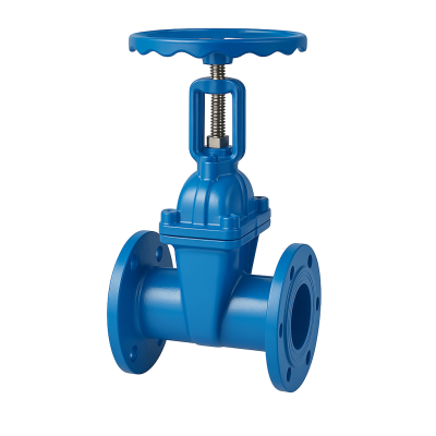
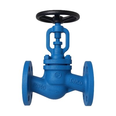
- Gate Valves
- Globe Valves
- Ball Valves
- Check Valves
- Bellow Type Valves
- Cryogenic Valves
- Strainers
Our ANSI valves are available in a wide range of designs with different features and functions. Some models operate automatically, while others can be manually, pneumatically, hydraulically, or electrically actuated. We are happy to assist you in selecting the right ANSI valve for your system.
ANSI Valves - American National Standards Institute
ANSI valves, or industrial valves according to ANSI standards (American National Standards Institute), are governed by a nonprofit, private American organization responsible for developing voluntary standards in the United States. Like DIN standards in Germany, ANSI standards are recommendations and not mandatory. They define the state of the art, technical norms, and regulatory frameworks.
In Germany, industrial valves built to ANSI standards are less commonly used.
Since the connection dimensions differ from those in DIN standards, ANSI valves are generally incompatible with German or European piping systems. For example, a gate valve with DIN connection dimensions cannot be installed in a pipeline built to ANSI specifications.

Components of Industrial Valves
The valve body, also known as the housing, is the primary component of a valve. It serves as the main structure that holds all other parts together. As the first pressure boundary of a valve, the body must withstand the fluid pressure from the connected pipelines. It links the inlet and outlet pipes through threaded, flanged, bolted, or welded connections.
The ends of the valve body are designed to connect the valve to the piping system—commonly via butt weld, socket weld, threaded, or flanged joints. Valve bodies are manufactured in a variety of shapes, typically cast or forged, with each design fulfilling a specific purpose. Every part is made from materials selected to suit its particular function and the demands of the process.
The bonnet is the cover for the opening of the valve body and is the second most important part of a pressure valve. Like valve bodies, bonnets come in various designs and models. It acts as a cover for the valve body, typically cast or forged from the same material as the body. The bonnet is usually attached to the body using threaded, bolted, or welded connections.
During valve assembly, internal components such as the stem, disc, or wedge are inserted into the body. The bonnet is then installed to secure all internal parts in place. In all cases, the connection between the bonnet and the valve body forms part of the valve’s pressure boundary—meaning the welds or bolts securing the bonnet are considered pressure-retaining components.
The removable and replaceable internal parts of a valve that come into contact with the flow medium are collectively referred to as the valve trim. These parts include the valve seats, disc, wedge, fasteners, spacers, guides, bushings, and internal springs. Components like the valve body, bonnet, and gaskets, although also in contact with the medium, are not considered part of the trim.
The trim is defined by the interface between the disc and the seat, as well as the relationship of the disc’s position to the seat. It is the trim that enables flow control and basic movement inside the valve. In rotary motion designs, the disc or wedge moves across the seat to regulate the flow opening. In linear motion trims, the disc lifts vertically from the seat, creating an annular opening.
Trim components are made from different materials depending on the varying forces and conditions they must withstand. For example, bushings and packing don’t experience the same stress as the valve disc and seats. Factors like flow medium properties, chemical composition, pressure, temperature, velocity, flow rate, and viscosity are important considerations when selecting suitable trim materials. The trim may or may not be made from the same material as the valve body or bonnet.
The disc is the component that allows, throttles, or stops flow depending on its position. When stopping the flow, the disc functions as the shut-off element. It represents the third most important primary pressure boundary in a valve. When the valve is closed, the entire system pressure is applied to the disc, which is why it must be considered a pressure-retaining part.
Discs are typically forged or cast and, in some designs, provided with a hard-facing material (such as Stellite) to ensure excellent wear resistance.
The seat or sealing rings provide the seating surface for the disc. A valve can have one or multiple seats. In the case of a check valve, there is usually a single seat that forms a seal with the disc to stop the flow. In the case of a shut-off valve, there are two seats: one on the upstream side and the other on the downstream side. A shut-off valve disc has two seating surfaces that come into contact with the valve seats to form a seal that stops the flow.
To improve the wear resistance of the sealing rings, the surface is often treated by overlay welding. A fine surface finish in the seat area is required to ensure a good seal when the valve is closed. Sealing rings are generally not considered pressure-retaining parts because the valve body has sufficient wall thickness to withstand the design pressure without relying on the thickness of the sealing rings.
The valve stem provides the necessary movement for the disc, plug, wedge, or ball and is responsible for opening or closing the valve, thus ensuring the correct positioning of the shut-off element. One end is connected to the valve handwheel or lever, while the other end is attached to the shut-off element. For gate valves or globe valves, a linear movement of the disc is required to open or close the valve, whereas for butterfly valves, ball valves, and plug valves, the disc is rotated to open or close the valve. Stems are typically forged and connected to the disc by threads or other methods. To prevent leakage, a fine surface finish is necessary in the sealing area of the stem.
The exterior of the stem is threaded, while the part of the stem inside the valve is smooth. The stem threads are isolated from the flowing medium by the packing gland. Two different styles of this design are available: one with the handwheel attached directly to the stem so they rise together, and the other with a threaded bushing that allows the stem to rise through the handwheel. This latter type is also known as an external stem thread. It is a common design for metal-sealed industrial valves.
The threaded portion of the stem is located inside the valve and does not rise. The plug of a globe valve moves like a nut along the stem when the stem is turned. Stem threads are exposed to the flowing medium and therefore subjected to pressure. This design is used when space is limited for linear movement and when the flowing medium does not cause erosion, corrosion, or abrasion of the stem material.
This is a commonly used design in ball valves, butterfly valves, or plug valves. A quarter-turn rotation of the stem opens or closes the valve.
For reliable sealing between the stem and the bonnet, a packing is required. This packing consists of several components, such as the gland ring, which is a sleeve that compresses the packing through a bushing into the gland. The gland flange is a type of flange that compresses the packing into the gland. The gland itself is a chamber where the packing is compressed. Packing materials are available in various types, including Teflon®, elastomers, fiber materials, graphite, and PTFE. A backseat seal is a seating arrangement within the bonnet that provides a seal between the stem and the bonnet, preventing system pressure from building up against the packing when the valve is fully open. Backseat seals are commonly used in gate valves and globe valves.
The valve yoke connects the valve body or bonnet to the actuator mechanism. The top of the yoke, which holds the yoke nut, stem nut, or yoke bushing and the valve stem, passes through it. A yoke typically has openings to allow access to the gland, stem, and other components. Structurally, the yoke must be strong enough to withstand the forces and torques generated by the actuator.
A yoke nut is an internally threaded nut located at the top of the yoke, through which the stem passes. In a gate valve, for example, the yoke nut is rotated, causing the stem to move up or down. In globe valves, the nut is fixed, and the stem is rotated through it. This page provides some basic information about industrial valves. If you have any further questions, we are happy to assist.
Our Workshop Service
- Disassembly and cleaning of the valve
- Inspection for wear and damage
- Procurement of spare parts
- Machining of sealing surfaces (seat/plug)
- Replacement of all seals
- Pressure and leakage testing
- Renewal of corrosion protection
- Painting work
Our On-Site Service:
- Analysis of the plant, industrial valves, and visual inspection
- spare parts management
- audit planning
- resource planning
- Customer service (24-hour availability)
- Logging / Documentation
- Corrective measures
- welding work


